"N1" Mono, Six Cell Stock,
El Lobo II
Setup by Ted Schultz
Parts List
1. Bandit Boats El Lobo II http://www.banditboats.com
2. Custom tuned 27 turn, 05 motor http://www.aggressiverctech.com
3. Fuller’s Fast Electric Hardware http://www.drcwebservices.com/ffe/
Part name Part numbers
a. 05 motor mount Fuller’s
b. Hughley motor coupler .125 x .130 OCFHE1813
c. Hughley .125 flex shaft OC4PS/OC130L-24A
d. .125 drive dog OC4D
e. .130 teflon tube drive shaft liner OC130T-24
f. 7/32 brass drive shaft tubing K&S
g. 2" strut bracket Fuller’s
h. Strut for .130 cable Fuller’s
i. "L" offset rudder arm bracket Fuller’s
j. Blade rudder Fuller’s
k. Rudder steering arm Fuller’s
l. Stainless steel turn fin and bracket Fuller’s
m. Dubro pushrod 12" Kwik Link DUB 108
n. Rubber boot assembly Bru Line 100
4. Misc. parts: many items can be found at Ultimate Hobbies Auburn, WA.
a. Antenna mount Hayes #185
b. Octura Y535 or X435 prop OCTY535/OCTX435
c. Octura Prop tail nut OC4PN
d. Lead/Teflon Sleeve bearings for strut OC4LTS
e. Thrust washer set for drive shaft OC4TW
f. 2" wide Velcro from Home Depot 90593
g. RC-Hydros' PG-612/ 60wBEC
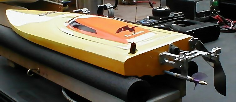
Basic Set-up for the El Lobo II
You can buy the running gear as individual pieces or purchase a hardware kit from Ray Fuller. I found Fuller’s Next Generation 6-12 cell mono hardware kit to be a savings over purchasing the items separately. Ray has even pre-soldered the prop shaft to the flex cable. He also includes a wedge rudder with water pickup. I have used it successfully however, Ray also offers a very nice blade rudder which I have found to be faster over the wedge rudder.
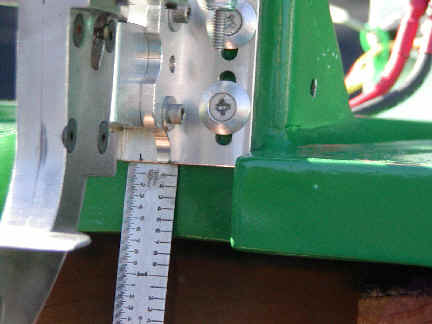
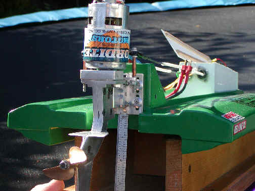
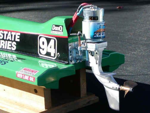
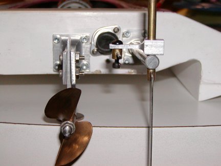
When drilling the transom for the shaft log I found Ray’s example in the picture below to be very helpful. Be sure to drill the center of the 7/32 hole ¼ inch up from the bottom of the keel. Carefully locate the strut bracket to the transom by assembling the strut into the bracket and align using Teflon tubing and prop shaft. Slide the bracket up strut to allow for plenty of height adjustment. Take your time with alignment. The four strut hole locations are very important and will ultimately determine how your boat can be tuned.
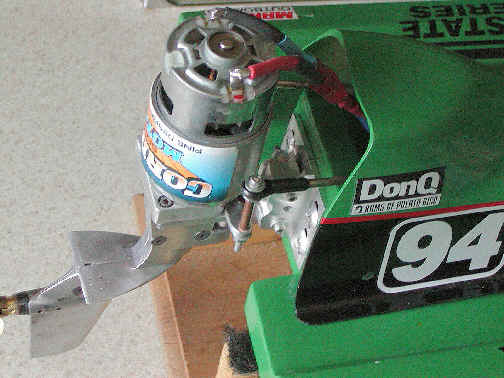
I chose not to use the older style rudder bracket; instead I used the new "L" shaped bracket shown in the diagram below. The "L" bracket attaches to the strut with (3) bolts. The rudder placement is offset at the same inch and a half location. I mounted the rubber boot assembly between the two locations for the rudder push rod. See example below.
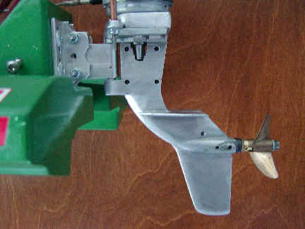
Hardware location for the El Lobo 2

I chose not to use trim tabs as shown here. After trying them I felt they were not needed in six cell stock class. The boat will easily balance out by using the saddle pack battery configuration. I have tried running all six cells in front of the motor but, it is too much weight forward resulting in keeping the nose too planted. Shifting the saddle packs fore and aft will allow you to fine tune your boat to various water conditions.
When mounting the turn fin as shown it is very responsive. I made my turn fin mounting bracket from aluminum angle. However you can also trim the right hand mounting flange from the bracket that comes with the turn fin and accomplish the same mounting location.
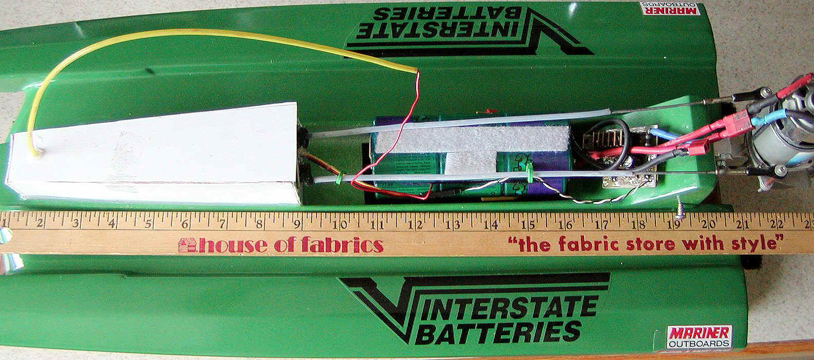
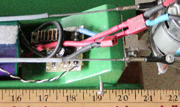
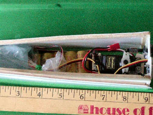
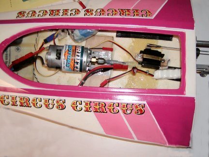
Interior Layout
In the figure above you will notice I mounted the ESC just ahead of the motor with the saddle packs on each side. This will help to keep the wires as short as possible for maximum power transfer. I prefer using Deans connectors on the batteries and ESC and Peak/Orion universal bullet type connectors on the motor.
I chose to use RC-Hydros' PG -612/60wBEC to save about 2 oz. of weight by not having to run a receiver pack. I had Andy make it with out the water cooling tubes to reduce even more weight. Using this configuration you can easily balance your boat to perform very well.
I would recommend using a good FM radio to minimize interference and provide good range. I am using a Hitec Lynx FM which has a very long antenna. It works very well on the water, in fact I can control my boat all the way across the lake, approximately a quarter mile away. The most common servo in our club for the rudder is the Hitec HS 225BB, however I switched to the lighter HS 81 to save even more weight.
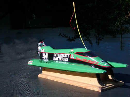
In the photo below I just applied full throttle after coming around the exit buoy. With careful trimming a tuned stock motor can easily reach speeds up to 35 mph or more.

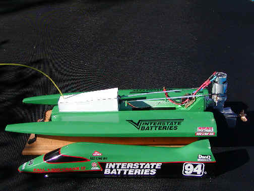
The Bandit boats El Lobo II is an all fiberglass hull designed for either "N1" Mono six cell stock class, "N2" six cell modified class or 8 cell "O" Mono class racing. Please reference set-ups for "N2" and "O" classes. Some of the racers in our club run vacuum formed plastic hulls that are about half the weight of a fiberglass hull. After a year of competition I found the heavier fiberglass hull to be just as competitive and much more durable. With a little fine tuning and paying attention to weight, not too many coats of paint, and lighter components, I am just as fast if not faster.
The biggest problem I have experienced this past year has been keeping the boat from torque rolling or flipping end over end. Typically most stock motors lack performance turning rpms in the range of 21,000 to 25,000 rpm. However, today’s new generation motors like the Trinity Monster Stock will turn 34,000 rpm or more with a good set of silver brushes. When tuned with AT30 XHS-LD 20% silver brushes using purple and green overhead springs when the brushes have fully seated it is not uncommon to experience rpms up to 36,000 rpm.
With this kind of performance in "N1" Mono, prop selection and prop tuning becomes a critical factor. A good basic prop to start with is the plastic Octura Y534. After a lot of experimentation my favorite is a cut down Octura X435. I have been removing most of the nose area of the blade to reduce drag which allows the motor to reach maximum rpm.
Other racers find that the Octura X632 work’s best for them. Lowering the strut height is key to running the smaller diameter props.
The latest new generation 3300 batteries have a higher average voltage and lower internal resistance over the earlier batteries. Make sure your connectors are up to the task of transferring the energy. The PG -612/60wBEC control limits average amp draw to 60 amps with peaks of 120 amps. A well tuned stock motor and a freshly peaked 3300 battery pack you will need to ease on the throttle to avoid doing a torque roll. This happened to me too many times to count. It is allot more fun to complete a race than to receive a DNS or DNF.
I hope this helps.
If you have any questions send me a email at www.aggressiverctech.com
Aggressive Ted
![]()
LS OPC Tunnel
Hull by 'Bandit
Boats'
Suggested setup by
Scott Bickford
Feel free to email me with any
questions
This the basic setup I use and I have won many races.
It's just a matter of finding your own sweet setup.
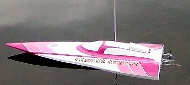
This
is a short setup for the bandit killer 'OPC' hull as it is being raced
now.
It has been lightened for running electric. The top and bottom hull
are stock configuration.

This
hull is 26" long by 10 1/2" wide. I have used a cut down
K&B lower unit with an 'SS1 700 BB'
motor with 12 matched GP 3300 stacked sub-C batteries. The picture below
shows the approximate location of
where the batteries will go from the cutout to the batteries.
As
you can see this is where the speed control is. It is from 'RC Hydros'
and is attached with velcro.
The ruler is in the same place measuring from the cutout as in the above
picture.
This is a picture of the
K&B 3.5 size lower unit that has been cut down. Also it shows a spacer
block between the SS 1 motor and the lower unit which matches for size and
is .40 thick.
This
picture shows the location of the mount from the bottom of the transom
which is
.60. The out drive is tipped 1 to 2 degrees from dead center with the
centerline of the prop at
the bottom of the sponsons.
This
side view shows the battery box that I made. The box measures 7 3/4"
long by 2 3/4" tall
and is 12" from the back of the transom. The width is as wide as the
molded opening. This
is a receiver, servo, battery box combo. The servo is a Futaba S3003. The
receiver is a 75 MHZ XXL by Novak.
The picture below shows the layout of the receiver, servo, battery box.
Some
people say that the cavitation plate should be removed. This picture shows
the
cavitation plate on and I have found that it gives me more stability. I'm
not saying it
should be left on but it works for me.
This
is just another view of the rear transom with the cowling on.
This
picture shows the height of the motor extending above the cowling. This
seems to
give better cooling for the SS 1Motor
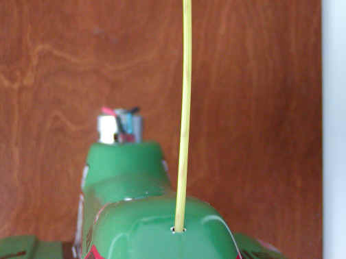
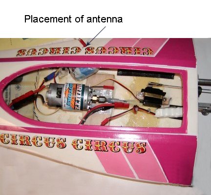
This picture shows the approximate location of the antenna.
![]()
Bandit "Bat Boat"
Hull design and setup by Scott
Bickford
setup for Limited Sport Hydro
sport running
1. Motor
mount: place
the mount on the center line of the boat, 7 inches from the outside of the
hull to the
vertical rise of the mount
2. Strut mount:
place the strut mount on the center line of the hull transom .060 from the
bottom
3. Adjustable Strut: adjust to 1 degree up and .055 from bottom of lowest part of sponsons
sitting on a flat
table. (.055 is approximately the thickness of a dime)
![]()
4. Rudder Mount: place mount 1 3/4 inch from center line of boat on right side
of the transom. The length
of the rudder extension rod is 2.60 inches from the transom
5.
Rudder:
a flat blade rudder is used for best stability
6.
Servo:
is offset to the right of inside centerline of boat .20 inches
to the nearest edge of
the servo. From the inside of the transom the servo is 2 3/4 inches
to the center line
of the servo
7.
Prop:
as tested-- polished and balanced X645
8.
Motor:
Graupner 700 BB SS1 (ref inside picture above)
9.
Receiver:
8 inches from inside of transom right of the center line as far as
possible
(ref inside picture above)
10. Antennae:
8 inches from outside of transom on the outside of the boat
11. Speed Control: 9 inches from the inside of
transom on the left side of center line tucked as far as
possible to inside of hull
12.
Batteries:
one 12 pack of 2400 series cells, split into two packs of 6 cells
each, placed 1/2 inch
on each side of center line and one cell forward of the inside of the
transom- attached
with Velcro for adjustment